Down Pressure Relief Valve

Part #K00022
- Adding a down pressure relief valve to your machine will limit the amount of broom down pressure an operator is allowed to put on the brush.
- Extends the life of the brush and reduces the stress put on the broom drive system.
BEFORE GETTING STARTED
- Ensure that all valves are closed to minimize hydraulic leak
- For field installation, a wrench will be needed to loosen and tighten the connections.
- In order to prevent the core arm from moving, be sure to use a jack stand to offer support before install
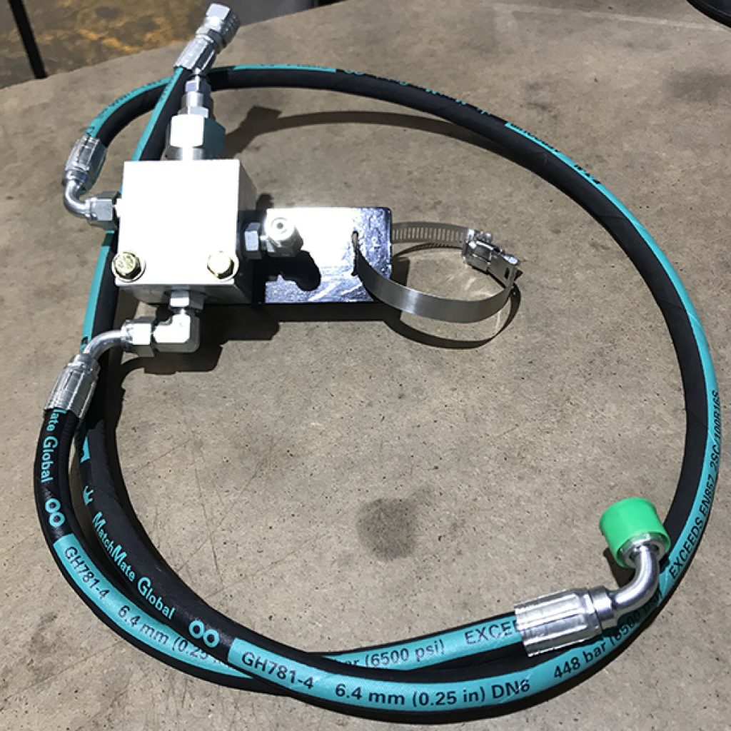
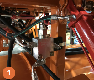
1. Assemble hoses to the relief valve body as shown in the above photo. Attach the kit on the post in front of the brush cover using the clamp provided. Optionally you can weld the bracket to the post.
2. Route long hose to back manifold. Note in the picture shown, how the longer hose has been run alongside other neighboring hoses.
2A. Remove the hydraulic hose from the lower end of the lift cylinder. Reattach to the post side of the relief valve (see circled in yellow). Attach free end of the shorter hose from the relief valve to the lower end of the cylinder.
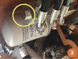
3. Remove the plug from the end of the manifold (see circled in yellow). Secure the 90 degree elbow into the manifold end so that the fitting end is facing vertical or forward.
4. Secure longer hydraulic hose end to the elbow.


