Scraper Blade
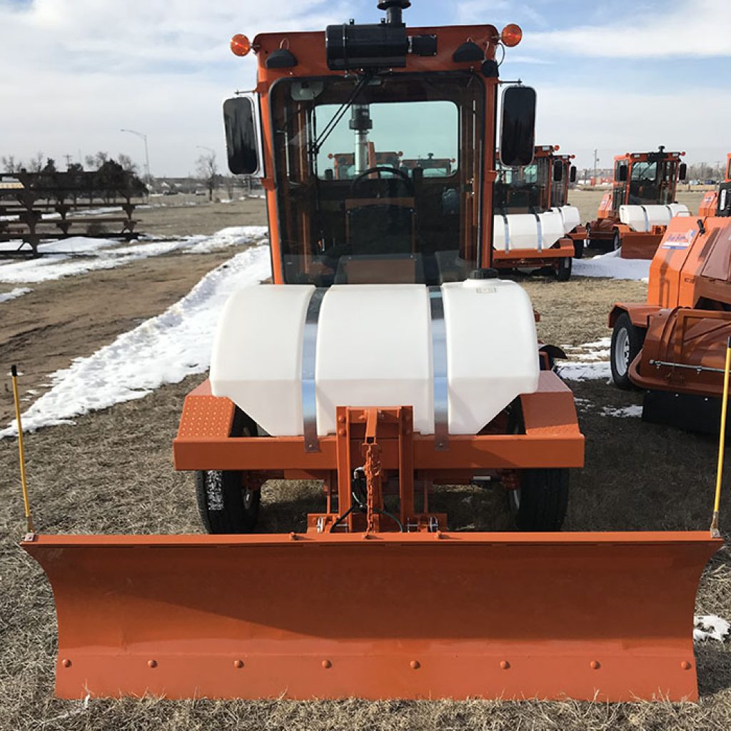
Part #4210P
- The scraper blade option allows for the movement of larger pieces than what a standard, brush-only unit might be capable of performing. Many customers who have a tendency to create large rocks, tree limbs or wood chunks, etc. prefer to use a combination of scraper blade and brush for their work.
BEFORE GETTING STARTED
- Unpack scraper blade assembly and parts from pallet.
- Remove keys from the machine
- Shut off 3 hydraulic 1/4 turn valves
- If your sweeper has a water tank installed, it will need to be removed before attaching the scraper blade.
The easiest way to proceed with the install is to start with the outside hardware first then finish up with the hardware inside the control box.
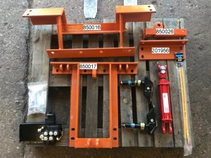
1. Once you have turned off the valves and removed the tank from the “before getting started” section, locate the components for the front ASM, frame mount (850016), lift frame (850017, blade lift arm WA (850026) and the frame brace (201956)
2. Locate the frame mount and attach to the underside of broom frame with the included hardware: four (4) 5/8” x 2 1/2” hex head bolts, 5/8” flat washers, 5/8” lock washers and 5/8” nuts. Do not tighten. Leave loose. It will wedge flat to the frame rails.
3. Next, mount the lift frame (850017) to the front of the frame mount (850016) using (4) 5/8” x 2 1/2” hex head bolts, 5/8” flat washers, 5/8” lock washers and 5/8” nuts. Make sure to keep it flush with the front bumper.
4. Locate the frame brace (201956) and attach to the back face of the lift frame (850017) using (4) 5/8” x 2 1/2” hex bolts, 5/8” flat washers, 5/8” lock washers and 5/8” nuts.
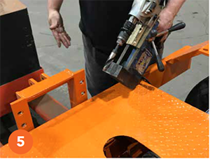
5. Use clamps to hold it in place. Using the frame brace as a guide, locate the top two holes on the broom frame and drill two 5/8” holes. Attach the frame brace to the top of the broom frame using (2) 5/8” x 2 1/2” hex bolts, 5/8” flat washers, 5/8” lock washers and 5/8” nuts.
6. Tighten up all 3 brackets.
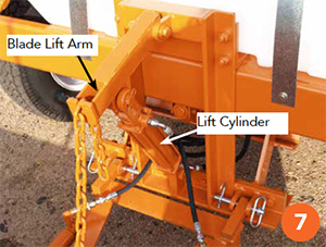
7. Install the blade lift arm WA (850026) to the lift frame (850017) using (1) 5/8” x 4” hexhead bolt, 5/8” lock washer, 5/8” nut.
8. Install the lift cylinder (208) to bottom of lift frame assembly (850017) and rod end of lift cylinder to the lift arm. Rod end needs to face up and the hydraulic ports to the left.
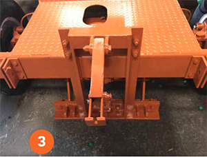
9. Mount the scraper blade ASM to the front of the machine.
10. Install the market kit (SBA02020)
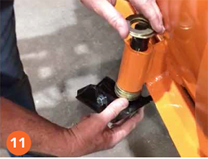
11. Install shoes to the scraper blade ASM.
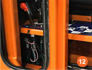
12. You will need to next remove the window in order to get access to the valve box cover.
13. Remove the side cover on the control box.
14. Clean the foam sealant from around the floor opening so that you can gain access through the floor to route the hoses.
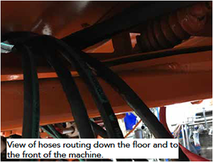
15. Locate the hydraulic hose at the broom spool valve marked with a (P) and remove and set to the side.
16. Cut out the opening marked “optional scraper valve”.
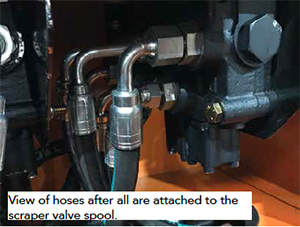
17. Install the new scraper valve, attached with supplied bolts. Next, you will start the installation of the hoses. All hoses will be marked with their size and part number.
18. Take the 29” hose marked with F387TCJ9J9060606-29 which is attached to the PB port on the left side of the scraper valve. Tighten. Attach the other end to the P port on the broom spool valve and tighten.
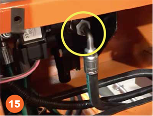
19. Next, locate the 31” hose marked with F387TCJ7J9060606-31. Attach the 90° hose end to the T port on the scraper valive. Route it through the floor going towards the rear of the machine.
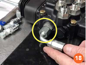
20. Remove the center plug on the return manifold and install the supplied adapter 608 90°.
21. Attach the 45° hose end to the adapter that is installed at the return manifold. Tighten the adapter and the hose end.
22. Locate the 127” hose marked with F387TCJ9J9060606-127. Attach 90° hose end at scraper valve spool 2, Port B (lower left).
23. Tighten and route down through the floor opening going towards the front of the machine (along right side frame rail).
24. Attach the 90° hose end to the rod end of the lift cylinder (top port) and tighten.
25. Locate the 114” marked F387TCJ9J1040404-114. Attach the long 90° fitting to scraper valve spool 2, Port A (upper left). Tighten and then route down through the floor opening going towards the front of the machine (along right side frame rail).
26. Attach the 90° hose end to the yoke end of the lift cylinder (bottom port).
27. Next, locate the 128” hose marked F387TCJCJ1040404-128. Attach the 90° hose end to the scraper valve spool 1, Port B (upper right). Tighten and then route down through the floor opening going towards the front of the machine (along right side frame rail).
28. Attach the straight hose end to the right side swing cylinder quick connect on the scraper blade.
29. Finally, locate the 129.5” hose marked with F387TCJCJ9040404-129.5. Attach the 90° hose end to the scraper spool 1, Port A (upper right). Tighten and then route down through the floor opening going towards the front of the machine (along right side frame rail).
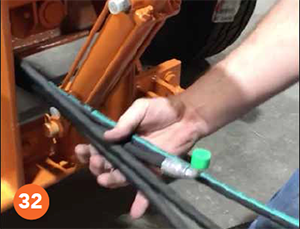
30. Attach the straight hose end to the left side swing cylinder quick connect on the scraper blade.
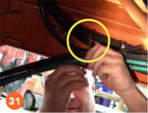
31. Secure the hose’s along the right side frame rail, using zip ties, to avoid any pinching and rubbing of the hoses while machine is in use.
32. Locate the first hydraulic hose removed from the broom 2 spool valve and attach it to the P Port on the scraper valve. Tighten.
33. Install the handle into the top of the
scraper valve.
34. Turn on 3 hydraulic 1/4 turn valve’s.
35. Replace machine keys.
36. Start the machine and test the operation of the new scraper valve and check for any hydraulic leaks.
37. Reseal the control box floor opening with Expand-a-foam to seal out dirt.
38. Reinstall the control box cover, window and water tank.
